-

Plastic encoder coupling
Product DescriptionShaft encoders must be protected against excessive mechanical stresses, which occur whenever there are angular, axial, or radial misalignments between the machine and shaft encoder shafts. Our flexible couplings can compensate for this within limits.
Hole Ø, mm:5 … 6Max. speed (rpm):10 000Torque max (N cm):20Moment of inertia (gcm2):1.1Torsional spring constant (Nm/rad):12Max. angular misalignment:±2.5°Max. shaft misalignment radial, mm:±0.3Max. shaft misalignment axial, mm:±0.2Max tightening torque of screws (N cm):70Material:polyamide 6.6 glass-fibre reinforced -

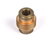
Helical encoder coupling 19/28
Product DescriptionShaft encoders must be connected to operated shaft and protected against excessive mechanical stresses, which occur whenever there are angular, axial, or radial misalignments between the machine and encoder shafts. At the same time the coupling needs to compensate for displacements without any big forces and positioning loss affecting the components of the encoder. Our flexible couplings can compensate for this within limits.
Hole Ø, mm:5 … 6,35Max. speed (rpm):6 000Torque max (N cm):80Moment of inertia (gcm2):8.7Torsional spring constant (Nm/rad):14Max. angular misalignment:±4°Max. shaft misalignment radial, mm:±0.25Max. shaft misalignment axial, mm:±0.4Max tightening torque of screws (N cm):80Material:AICuMgPb, chromed -
Helical encoder coupling 25/32
Product DescriptionShaft encoders must be connected to operated shaft and protected against excessive mechanical stresses, which occur whenever there are angular, axial, or radial misalignments between the machine and encoder shafts. At the same time the coupling needs to compensate for displacements without any big forces and positioning loss affecting the components of the encoder. Our flexible couplings can compensate for this within limits.
Hole Ø, mm:6 … 10Max. speed (rpm):6 000Torque max (N cm):80Moment of inertia (gcm2):8.7Torsional spring constant (Nm/rad):14Max. angular misalignment:±4°Max. shaft misalignment radial, mm:±0.25Max. shaft misalignment axial, mm:±0.4Max tightening torque of screws (N cm):80Material:AICuMgPb, chromed -

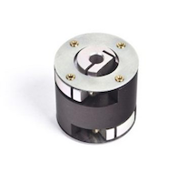
Disc encoder coupling
Product DescriptionShaft encoders must be connected to operated shaft and protected against excessive mechanical stresses, which occur whenever there are angular, axial, or radial misalignments between the machine and encoder shafts. At the same time the coupling needs to compensate for displacements without any big forces and positioning loss affecting the components of the encoder. Our flexible couplings can compensate for this within limits. Disc coupling usually affects less position loss.
Hole Ø, mm:6Max. speed (rpm):12 000Torque max (N cm):80Moment of inertia (gcm2):19Torsional spring constant (Nm/rad):150Max. angular misalignment:±3°Max. shaft misalignment radial, mm:±0.4Max. shaft misalignment axial, mm:±0.4Max tightening torque of screws (N cm):80Material:AICuMgPb, anodized, stainless steel -

Isolated disc encoder coupling
Product DescriptionShaft encoders must be connected to operated shaft and protected against excessive mechanical stresses, which occur whenever there are angular, axial, or radial misalignments between the machine and encoder shafts. At the same time the coupling needs to compensate for displacements without any big forces and positioning loss affecting the components of the encoder. Our flexible couplings can compensate for this within limits.
Hole Ø, mm:5 … 10Max. speed (rpm):12 000Torque max (N cm):60Moment of inertia (gcm2):19Torsional spring constant (Nm/rad):30Max. angular misalignment:±2,5°Max. shaft misalignment radial, mm:±0.3Max. shaft misalignment axial, mm:±0.4Material:aluminium, anodized, plastic, glass-fibre reinforced -

Disc encoder coupling LIR-800
Product DescriptionShaft encoders must be connected to operated shaft and protected against excessive mechanical stresses, which occur whenever there are angular, axial, or radial misalignments between the machine and encoder shafts. At the same time the coupling needs to compensate for displacements without any big forces and positioning loss affecting the components of the encoder. Our flexible couplings can compensate for this within limits. Disc coupling usually affects less position loss.
Hole Ø, mm:3 … 4Max. speed (rpm):10 000Torque max (N cm):4Moment of inertia (gcm2):1,9Torsional spring constant (Nm/rad):50Max. angular misalignment:±0,5°Max. shaft misalignment radial, mm:±0.2Max. shaft misalignment axial, mm:±0.2 -
Disc encoder coupling LIR-801
Product DescriptionShaft encoders must be connected to operated shaft and protected against excessive mechanical stresses, which occur whenever there are angular, axial, or radial misalignments between the machine and encoder shafts. At the same time the coupling needs to compensate for displacements without any big forces and positioning loss affecting the components of the encoder. Our flexible couplings can compensate for this within limits. Disc coupling usually affects less position loss. LIR-801 suitable for most industrial encoders with solid shaft diameters 3 to 10 mm.
Hole Ø, mm:3 … 10Max. speed (rpm):10 000Torque max (N cm):10Moment of inertia (gcm2):30Torsional spring constant (Nm/rad):150Max. angular misalignment:±1°Max. shaft misalignment radial, mm:±0.2Max. shaft misalignment axial, mm:±0.2 -

Bellows encoder coupling
Product DescriptionShaft encoders must be connected to operated shaft and protected against excessive mechanical stresses, which occur whenever there are angular, axial, or radial misalignments between the machine and encoder shafts. At the same time the coupling needs to compensate for displacements without any big forces and positioning loss affecting the components of the encoder. Our flexible couplings can compensate for this within limits. Bellows coupling usually compensate higher misalignment.
Hole Ø, mm:6 … 12Max. speed (rpm):8 000Torque max (N cm):80Moment of inertia (gcm2):9Torsional spring constant (Nm/rad):140Max. angular misalignment:±4°Max. shaft misalignment radial, mm:±0.3Max. shaft misalignment axial, mm:±0.5Max tightening torque of screws (N cm):150Material:aluminium, stainless steel -

Bellows encoder coupling LIR-814
Product DescriptionShaft encoders must be connected to operated shaft and protected against excessive mechanical stresses, which occur whenever there are angular, axial, or radial misalignments between the machine and encoder shafts. At the same time the coupling needs to compensate for displacements without any big forces and positioning loss affecting the components of the encoder. Our flexible couplings can compensate for this within limits. Bellows coupling usually compensate higher misalignment.
Hole Ø, mm:3 … 6Max. speed (rpm):12 000Torque max (N cm):10Moment of inertia (gcm2):2,5Torsional spring constant (Nm/rad):40Max. angular misalignment:±1°Max. shaft misalignment radial, mm:±0.2Max. shaft misalignment axial, mm:±0.5 -
Bellows encoder coupling LIR-825
Product DescriptionShaft encoders must be connected to operated shaft and protected against excessive mechanical stresses, which occur whenever there are angular, axial, or radial misalignments between the machine and encoder shafts. At the same time the coupling needs to compensate for displacements without any big forces and positioning loss affecting the components of the encoder. Our flexible couplings can compensate for this within limits. Bellows couplings usually compensate bigger shaft misalignment. LIR-825 suitable for most industrial encoders with solid shaft diameters 4 to 12 mm.
Hole Ø, mm:4 … 12Max. speed (rpm):12 000Torque max (N cm):10Moment of inertia (gcm2):18Torsional spring constant (Nm/rad):130Max. angular misalignment:±1°Max. shaft misalignment radial, mm:±0.2Max. shaft misalignment axial, mm:±1 -

High precision encoder coupling LIR-803
Product DescriptionShaft encoders must be connected to operated shaft and protected against excessive mechanical stresses, which occur whenever there are angular, axial, or radial misalignments between the machine and encoder shafts. At the same time the coupling needs to compensate for displacements without any big forces and positioning loss affecting the components of the encoder. Our precision couplings provide minimal position loss.
Hole Ø, mm:10; 14Max. speed (rpm):3000Torque max (N cm):50Moment of inertia (gcm2):200Torsional spring constant (Nm/rad):4000Max. angular misalignment:±0,5°Max. shaft misalignment radial, mm:±0.3Max. shaft misalignment axial, mm:±0.2 -

High precision encoder coupling LIR-805
Product DescriptionShaft encoders must be connected to operated shaft and protected against excessive mechanical stresses, which occur whenever there are angular, axial, or radial misalignments between the machine and encoder shafts. At the same time the coupling needs to compensate for displacements without any big forces and positioning loss affecting the components of the encoder. Our precision couplings provide minimal position loss.
Hole Ø, mm:14Max. speed (rpm):1000Torque max (N cm):100Moment of inertia (gcm2):200Torsional spring constant (Nm/rad):6000Max. angular misalignment:±1°Max. shaft misalignment radial, mm:±0.3Max. shaft misalignment axial, mm:±0.1 -

Measuring wheels
Product DescriptionMeasuring wheels in combination with rotary encoder allows to measure direct linear motion. Diameter (Circumference) and tread depending on application. In order to prevent the result being distorted when the shaft encoder is driven by a measuring wheel make sure that the slip is as small as possible. When selecting the tread (surface), take into account the structure, stretchability, thickness, and resistance to being carried along of the material being measured. The slip is also affected by the width of the measuring wheel, the contact pressure, the tension in the material being measured, and the arc of contact. The arc of contact should be as large as possible. The wheel bodies are made of cast aluminium or plastic (as marked). The position of the measuring wheel should be chosen so that the direction of movement of the material is away from the shaft encoder’s bearing point.
Diameter, mm:5,73 … 15,92Circumference, mm:182,88 … 500Bore ø, mm:4 … 12Material:Aluminium / PlasticWidth of surface, mm:4 … 25Tread 1:with rim and fine crosshatched knurl Material: aluminiumTread 2A:soft specially clinging rubber surface (red)Tread 2B:low-wear rubber surface with good grip (white)Tread 3:vulcanized rubber surface with parallel knurlTread 4:aluminium with parallel knurlTread 5:with rim, aluminium with parallel knurlTread 6:plastic surface
- Products
- By industry
- Encoder Wiki
- About us
- Contacts